
Types Of Current Transformers And Their Functions
Current transformers (CTs) are an essential component in electrical systems, particularly in the power distribution and transmission industry. These devices are used to measure the current flowing in a circuit and provide a reduced output current that can be easily read by instruments or meters. There are several types of current transformers available, each with its own unique features and applications. In this article, we will explore the different types of current transformers and their uses in the electrical industry.
Types of Current Transformers
There are four major types of current transformers: Window-type, which includes bushing-type (BCT); bar-type; split-core-type; and wound-type, the latter having both a primary and secondary winding.
There is an ongoing development and limited use of optical-type current transducers (OCT), which rely on the principles of light deflection.
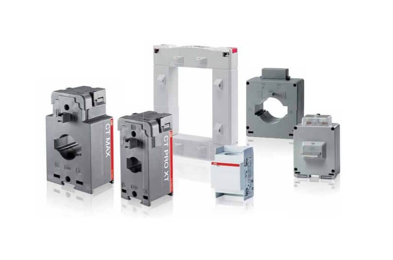
1. Window-type current transformer
The window-type current transformer is the simplest form of instrument transformer. It is considered to be an incomplete transformer assembly since it consists only of a secondary winding wound on its core.
The most common type is that wound on a toroidal core. The secondary winding is fully distributed around the periphery of the core. In special cases when taps are employed, they are distributed such that any connection made would utilize the entire core-periphery. Windings in this manner ensure optimum flux linkage and distribution. Coupling is almost impervious to the primary-conductor position, provided that the return path is sufficiently distanced from the outer periphery of the secondary winding.

The effects of stray flux are negligible, thus making this type of winding a low-reactance design. The primary winding in most cases is a single conductor centrally located in the window. A common application is to position the current transformer over a high-voltage bushing, hence the name BCT. Nearly all window-type current transformers manufactured today are rated 600 V class. In practice, they are intended to be used over insulated conductors when the conductor voltage exceeds 600 V. It is common practice to utilize a 600 V class window type in conjunction with air space between the window and the conductor on higher-voltage systems. Such use may be seen in isolated-phase bus compartments. Some window types can be rated for higher voltages as stand-alone units, for use with an integral high-voltage stress shield, or use with an insulating sleeve or tube made of porcelain or some polymeric material. Window-type current transformers generally have a round window opening but are also available with rectangular and oval openings. This is sometimes provided to fit a specific bus arrangement found in the rear of switchgear panels or on draw-out-type circuit breakers. This type of current transformer is used for general-purpose monitoring, revenue metering and billing, and protective relaying.
2. Bar-Type current transformer
The bar-type current transformer is, for all practical purposes, a window-type current transformer with a primary bar inserted straight through the window.

This bar assembly can be permanently attached or held in place with brackets. Either way, the primary conductor is a single turn through the window, fully insulated from the secondary winding. The bar must be sized to handle the continuous current to be passed through it, and it must be mechanically secured to handle high-level short-circuit currents without incurring damage. The uses are the same as the window type.
3. Split-Core type current transformer
The split-core type current transformer is a special case of a window-type current transformer. Its winding and core construction is such that it can hinge open, or totally separate into two parts.
This arrangement is ideal to use in cases where the primary conductor cannot be opened or broken. However, because of this cut, the winding is not fully distributed.

Often only 50% of the effective magnetic path is used. The use of this type should be with discretion since this construction results in higher-than-normal errors. There is also some uncertainty in the repeatability of performance from installation to installation.
The reassembly of the core halves is critical. It is best suited for general-purpose monitoring and temporary installations.
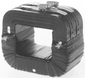
4. Wound-Type current transformer
The wound-type current transformer is a special type of CT that has a primary winding that is fully insulated from the secondary winding. Both windings are permanently assembled on the core.

The insulation medium used whether polymeric, oil or even air-in conjunction with its rated voltage class dictates the core and coil construction. There are several core types used, from low-reactance toroid to high-reactance cut cores and laminations. The distribution of the cut(s) and gap(s) helps control the magnetizing losses. The manner in which the windings are arranged on the core affects the reactance since it is a geometric function. Generally, the windings do not utilize the magnetic path efficiently. The proper combination of core type and coil arrangement can greatly reduce the total reactance, thus reducing errors.

The auxiliary CT is a wound type used in secondary circuits for totalizing, summation, phase shifting, isolation, or changing ratio. They are typically 600 V class since they are used in the low-voltage circuit.

When applying auxiliary CTs, the user must be aware of their reflected impedance on the mainline CT.
“Expand your knowledge on electrical transformers and rotating machines with this comprehensive guidebook by Stephen L. Herman. Get your copy on Amazon today and elevate your expertise in the field!”
 Best Electrical Tapes for Outdoor Use: Buying Guide
  What is an Arc Flash Relay? How Does it Work?
  What is a Dual Function Circuit Interrupter? And Its Function
  Advantages and Disadvantages of Incandescent Lamps
  VFD Parts: A Guide to Their Essential Functions
  Applications of 3-Phase Induction Motors in Industries