What is a Micro Switch: Explained With Working Principle

Whether it be the industrial, construction, agriculture, commercial, or transportation industry, the micro switch has become an integral part of the sensing and control community. There are perhaps trillions of micro switches in use at this very moment in various types of industrial equipment, agriculture or construction machinery, and control systems around the globe. The fact that such a simple device – with normally open or closed contacts coupled with a snap-action switching mechanism – is capable of performing at an enhanced precision level, reliably and safely, in the many harsh environments, is simply astonishing.
What is a Micro Switch?
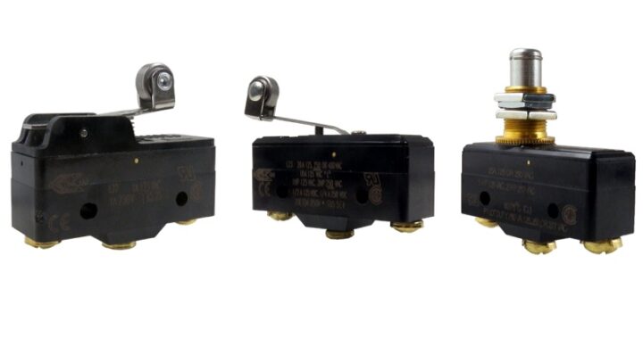
A micro switch is a snap-action precision changeover switch with a very small contact gap. The snap-action defines a changeover switch whereby contact-making and breaking speed are independent of the operating speed of the actuator. It is also referred to as a miniature snap-action switch.
Compared to conventional switches, micro switches have the following distinctive characteristics:
- Reduced size.
- Reduced operating travel: tenths of a millimeter.
- Increased electrical properties.
- Increased service life.
- Reduced sensitivity to vibrations and high accelerations.
Microswitches are often best suited for presence and absence detection where physical contact with an object is permissible. They also excel in applications requiring simple on-and-off actions. Each switch contains a spring and a set of contacts that convert mechanical energy applied to an actuator/plunger into an electrical output.
These switches are ideal where saving space and weight are important.
How Does a Micro Switch Work?
The micro switch makes physical contact with an object. After that, contacts change position.
The basic working principle is as follows:
When the plunger is in the released or rest position
- The normally closed circuit can carry current.
- The normally open circuit is electrically insulated.
When the plunger is depressed or switched
- The normally closed circuit is open.
- The normally open circuit is closed.

Construction of a Micro Switch
The construction of a microswitch is really simple. The main parts of the switch are:
1. Plunger (Actuator), 2. Cover, 3. Moving piece, 4. Support, 5. Case, 6. NO terminal, 7. NC terminal, 8. Contact, 9. Moving arm

Examples of actuators

Definitions of Operating Characteristics
The definitions below explain the meaning of operating characteristics. Sketches show how characteristics are measured for in-line plunger actuation. Linear dimensions for in-line actuation are from the top of the plunger to a reference line, usually the center of the mounting holes.
Differential Travel (D.T.)
The plunger or actuator travels from the point where contacts ‘‘snap-over’’ to the point where they ‘‘snapback.
Free Position (F.P.)
Position of switch plunger or actuator when no external force is applied (other than gravity).
Full Overtravel Force
Force required to attain full overtravel of the actuator.
Operating Position (O.P.)
Position of switch plunger or actuator at which point contacts snap from normal to operating position. Note that in the case of flexible or adjustable actuators, the operating position is measured from the end of the lever or its maximum length.
Operating Force (O.F.)
Amount of force applied to switch plunger or actuator to cause contact ‘‘snap-over.’’ Note in the case of adjustable actuators, the force is measured from the maximum length position of the lever.
Overtravel (O.T.)
Plunger or actuator travel safely available beyond the operating position.
Pretravel (P.T.)
Distance or angle traveled in moving plunger or actuator from free position to operating position.
Release Force (R.F.)
Amount of force still applied to switch plunger or actuator at moment contacts snap from operated position to unoperated position.
Total Travel (T.T.)
Distance from actuator free position to overtravel limit position.


Terms related to durability
Mechanical Durability
The switching durability is when a switch is operated at a specified frequency and specified overtravel (OT) without the contacts energized.
Electrical Durability
The switching durability is when a switch is operated at a specified frequency and specified overtravel (OT) under the rated load.
Maintenance
Microswitches are not user-maintainable but they should be kept in a reasonably clean, paint-free condition, especially in the actuator area. Regular checks should be made on mounting security and on the actuating medium to switch actuator relationships. Lubrication or the use of aqueous or chemical cleaning fluids is not recommended.
Do not use switches in atmospheres containing combustible or explosive gases. Arc or heat generated by switching may cause fires or explosions. Do not drop or disassemble switches. Not only will characteristics be jeopardized, but also damage, electric shock, or burning may result.
Mounting
Side mounting switches should be mounted on smooth, firm, flat surfaces using the recommended screw size. Avoid over-tightening the screws. For added security, they should be locked using epoxy resin. Do not attempt to enlarge switch mounting holes and avoid over-stressing the switch. Use insulating material between the switch and metallic plates to increase clearance on switches with open terminals.
When soldering, overheating of the switch insulation must be avoided. In certain circumstances, it may be advisable to use a heat shunt. For optimum mechanical strength, the conductor should be wrapped around the tip of the terminal taking care to avoid loose strands of wire.

 Types of Timer Relays and Their Applications
  Relay Applications: Real-Life And Industrial Examples
  Types of Micro Switches and Their Applications
  Best Voltage Testers for Home Use: 2023 Edition
  Advantages of Transducers for Optimal Measurement
  Advantages of Infrared Sensors: Improved Accuracy and More