
Understanding Oscilloscope Controls and Their Functions

An oscilloscope is a powerful tool used in the field of electronics to measure and analyze electrical signals. At its core, an oscilloscope is a device that displays the voltage of an electrical signal over time, allowing engineers and technicians to visualize and understand the behavior of complex electronic systems. In order to effectively use an oscilloscope, it is important to understand the various controls and functions available on the device. This article will explore the different controls and functions of an oscilloscope and how they are used in the measurement and analysis of electrical signals.
Oscilloscope Controls and Their Functions
The following is a list of common controls found on the oscilloscope:
1. Power
The power switch is used to turn the oscilloscope ON or OFF.
2. Beam Finder
This control is used to locate the position of the trace if it is off the display. The BEAM FINDER button will indicate the approximate location of the trace. The position controls are then used to move the traceback on the display.
3. Probe Adjust
This is a reference voltage point used when compensating the probe. Most probes adjust points to produce a square wave signal of about 0.5 volts.
4. Intensity and Focus
The INTENSITY control adjusts the brightness of the trace. A bright spot should never be left on the display because it will burn a spot on the face of the cathode ray tube (CRT). This burned spot results in permanent damage to the CRT. The FOCUS control sharpens the image of the trace.
5. Vertical Position
This is used to adjust the trace up or down on the display. If a dual-trace oscilloscope is being used, there will be two vertical POSITION controls. (A dual-trace oscilloscope contains two separate traces that can be used separately or together.)
6. CH 1–BOTH–CH 2
This control determines which channel of a dual-trace oscilloscope is to be used, or whether they are both to be used at the same time.
7. ADD–ALT–CHOP
This control is active only when both traces are displayed at the same time.
The ADD adds the two waves together.
ALT stands for alternate. This alternates the sweep between Channel 1 and Channel 2.
The CHOP mode alternates several times during one sweep. This generally makes the display appear more stable. The CHOP mode is generally used when displaying two traces at the same time.
8. AC–GND–DC
The AC is used to block any DC voltage when only the AC portion of the voltage is to be seen. For instance, assume an AC voltage of a few millivolts is riding on a DC voltage of several hundred volts. If the voltage range is set high enough so that 100 VDC can be seen on the display, the AC voltage cannot be seen. The AC section of this switch inserts a capacitor in series with the probe. The capacitor blocks the DC voltage and permits the AC voltage to pass. Because the 100 VDC has been blocked, the voltage range can be adjusted for millivolts per division, which will permit the AC signal to be seen.
The GND section of the switch stands for ground. This section grounds the input so the sweep can be adjusted for 0 volt at any position on the display. The ground switch grounds at the scope and does not ground the probe. This permits the ground switch to be used when the probe is connected to a live circuit. The DC section permits the oscilloscope to display all of the voltage, both AC and DC, connected to the probe.
9. Horizontal Position
This control adjusts the position of the trace from left to right.
10. Auto–Normal
This determines whether the time base will be triggered automatically or operated in a free-running mode. If this control is operated in the NORM setting, the trigger signal is taken from the line to which the probe is connected. The scope is generally operated with the trigger set in the AUTO position.
11. Level
The LEVEL control determines the amplitude of the signal must be before the scope triggers.
12. Slope
The SLOPE permits selection as to whether the trace is triggered by a negative or positive waveform.
13. INT.–LINE–EXT
The INT. stands for internal. The scope is generally operated in this mode. In this setting, the trigger signal is provided by the scope. In the LINE mode, the trigger signal is provided from a sample of the line. The EXT or external, mode permits the trigger pulse to be applied from an external source.
Note: These are the major controls. Most oscilloscopes contain these controls.
 Types of Timer Relays and Their Applications
  Relay Applications: Real-Life And Industrial Examples
 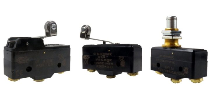 Types of Micro Switches and Their Applications
 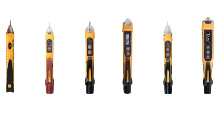 Best Voltage Testers for Home Use: 2023 Edition
  Advantages of Transducers for Optimal Measurement
  Advantages of Infrared Sensors: Improved Accuracy and More