
What is a Safety Foot Switch: Function, Applications, Types

A Safety Foot Switch is an important component in many industrial settings as it provides a safe and convenient method of controlling various equipment and machines. The working principle of this device is straightforward – it operates through the use of pressure applied to the switch by the operator’s foot. This allows the operator to control the machine without having to use their hands which enhances the overall safety and efficiency of the operation. In this article, we will explore the working principle, applications and types of Safety Foot Switches in detail.
What is a Safety Foot Switch?
A safety foot switch is a device that is designed to provide an added level of safety in industrial and commercial settings. These switches are typically used in areas where machinery or equipment is in operation, and can be used to shut off power to the equipment in the event of an emergency or other safety hazard.
They are often used in conjunction with other safety devices, such as emergency stop buttons or safety guards, to ensure that workers are protected from potential hazards.

Safety Foot Switch Working Principle
The safety foot switch has two contact blocks, each with one NO contact and one NC contact. Two contact blocks are connected for easy connection of a single-phase motor. (1) The normal workflow is initiated by pressing down the pedal as far as the pressure point so that the two NO contacts close and the motor starts to run. (2)
If in the event of danger, the pedal is pressed beyond the resistance of the pressure point, the positively driven NC contacts will open and the motor is stopped. (3) At the same time, the independent latching takes effect and holds the NC contacts in the open position. This prevents the machine parts from continuing to run out of control or from being restarted.
After the hazard is eliminated, the machine can only be restarted after manually releasing the switch using a pushbutton on the top of the enclosure. (4) The contacts are then released again and return to their initial position (the NO contacts are open and the NC contacts are closed). (5)

Safety Foot Switch Applications
The foot-operated safety switch has been developed for industrial applications with high mechanical and electrical endurance. The safety foot switch can be used in machines such as:
- Adhesive dispensers
- Abrasive blasters
- Packaging equipment
- Conveyors
- Material handling equipment
- Man lifts
- Communications equipment
- Lighting
- Engine brake
- Alarms / Security
- Emergency vehicles – Siren / Horn
- Terminal applicators
- Degreasers
- Metalworking machines
- Electric vehicles
- Farm equipment
- Engravers machinery
- Scissor lifts
- Riveting machinery
- Soldering / Desoldering / UV Curing / Welding Equipment

Safety Foot Switch Types
Safety foot switches come in three operation formats.
1-Free movement
Contact position follows pedal movement: actuated when the pedal is pushed down, released when the pedal is in a state of rest.

2-Foot switch locked in the neutral position
The same operation as above, after unlocking the pedal with the end of the foot.

3-Foot switch latched in the low position
The same operation as free movement, except that a state of rest is obtained only after having unlatched the pedal with the end of the foot.

Safety Foot Switch Construction

Safety Foot Switch Selection Parameters
The type or model of safety foot switch suitable for each application will vary depending on factors such as the control function required, degree of protection required, production methods, unusual conditions, government regulations, etc. In some applications, more than one switch may be required, as when two or more persons are operating a machine. In these cases, safe practices and regulations require that the switches be wired in series making it necessary that each operator’s foot switch be actuated before the machine will cycle.
Only the user can be aware of all the conditions and factors present during the setup, operation, and maintenance of the machine; therefore, only the user can determine which foot switch(es) can be properly used. When selecting a foot switch for a particular application, the user should refer to the applicable ANSI standards and OSHA regulations. The National Safety Council’s Accident Prevention Manual also provides much useful information.
In some applications, such as power presses, additional operator protection such as point-of-operation guarding must be provided when a foot switch is used as an actuator. This is necessary since the operator’s hands and other parts of the body are free to enter the pinch point area and serious injury can occur. The shielding provided by them cannot protect an operator from injury. For this reason, the safety foot switch cannot be substituted for or take the place of point-of-operation protection.
Safety Foot Switch Maintenance
Every week: Check the correct operation of the pedals. Remove all dirt or particles on the switch that may affect function. Check enclosure and cable for damages and impurities.
Every 6 months: Lubricate the cam and roller shafts. Isolate power and remove the cover. Check screw terminal tightness and check for signs of moisture ingress.
 Types of Timer Relays and Their Applications
  Relay Applications: Real-Life And Industrial Examples
 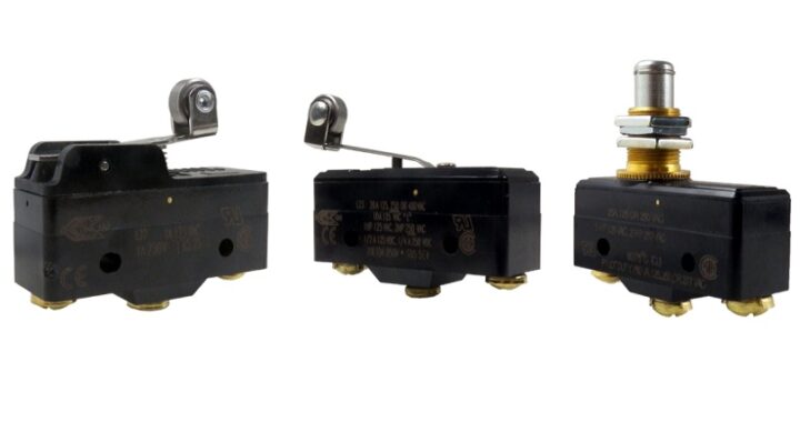 Types of Micro Switches and Their Applications
 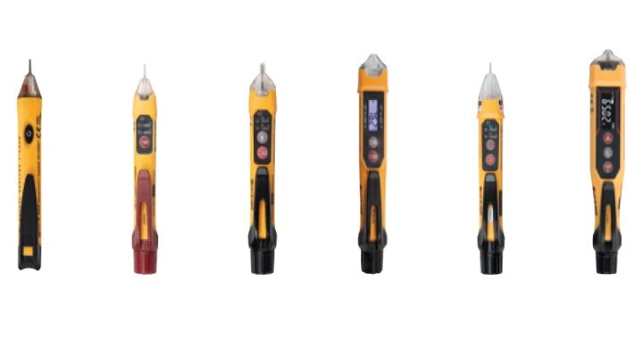 Best Voltage Testers for Home Use: 2023 Edition
  Advantages of Transducers for Optimal Measurement
  Advantages of Infrared Sensors: Improved Accuracy and More