
What is a Solid State Contactor? How Does it Work?

What is a Solid State Contactor?
A solid-state contactor is an electronic switch that controls the flow of electricity in an electrical circuit. Unlike traditional mechanical contactors, which use physical components to make and break connections, solid-state contactors use semiconductor devices such as transistors, diodes and thyristors to switch the electrical current.
This results in a compact, reliable and low-noise device that is ideal for use in high-speed and high-frequency applications, as well as in harsh environments where traditional contactors may fail. Solid-state switching refers to the interruption of power by nonmechanical electronic means. The figure below shows a single-pole AC solid-state contactor that uses electronic switching. In contrast to a magnetic contactor, an electronic contactor is absolutely silent and its “contacts” never wear out. Static contactors are recommended in applications that require a high switching frequency such as heating circuits, dryers, single- and three-pole motors and other industrial applications.

How Does a Solid State Contactor Work?
The most common high-power switching semiconductor used in solid-state contactors is the silicon-controlled rectifier (SCR). An SCR is a three-terminal semiconductor device (anode, cathode and gate) that acts like the power contact of a magnetic contactor. A gate signal, instead of an electromagnetic coil, is used to turn the device on, allowing current to pass from the cathode to the anode. The figure below shows three types of SCR construction styles designed for higher-current applications: the disk (also known as puck type), stud mount and module. Flexible-lead stud-mounted SCRs have a gate wire, a flexible cathode lead and a smaller cathode lead that is used only for control purposes. The heat generated by the SCR must be dissipated; thus all contactors have some means to cool the SCR. Typically an aluminum heat sink, with fins to increase the surface area, is used to dissipate this energy into the air.

The SCR, like a contact, is in either the on state (closed contact) or the off state (open contact). SCRs are normally off switches that can be triggered by a small current pulse into the gate electrode. Once turned on (or triggered ), the component then stays in the conducting state even when the gate-on signal is removed. It returns to the off (blocking) state only if the anode-to-cathode current falls below a certain minimum or if the direction of the current is reversed. In this respect, the SCR is analogous to a latched contactor circuit—once the SCR is triggered, it will stay on until its current decreases to zero. The SCR testing circuit shown in the below figure is practical both as a diagnostic tool for checking suspected SCRs and as an aid to understanding how they operate.

The operation of the circuit can be summarized as follows:
- A DC voltage source is used for powering the circuit and two pushbutton switches are used to latch and unlatch the SCR, respectively.
- Momentarily closing the on-push button connects the gate to the anode, allowing current to flow from the negative terminal of the battery, through the cathode-gate junction, through the switch, through the bulb and back to the battery.
- This gate current should cause the SCR to latch on, allowing the current to go directly from the cathode to the anode without further triggering through the gate.
- Momentarily opening the normally closed-off push button interrupts the current flow to the SCR and bulb. The light turns off and remains off until the SCR is triggered back into conduction.
- If the bulb lights at all times, this is an indication that the SCR is shorted.
- If the bulb fails to light when the SCR is triggered into operation, this is an indication that the SCR is faulted open.
Since an SCR passes current in one direction only, two SCRs are necessary to switch single-phase AC power. The two SCRs are connected inverse-parallel (back-to-back): one to pass current during the positive half-cycle and the other during the negative half-cycle. Half the current is carried by each SCR and sinusoidal AC current flows through the resistive load R when gates G1 and G2 are fired at 0 degrees and 180 degrees of the input, respectively.

Inductive loads and voltage transients are both seen as problem areas in solid-state AC contactor control because they could falsely trigger an SCR into conduction. For this reason, for driving an inductive load, a snubber circuit is used to improve the switching behavior of the SCR. The figure below shows an electronic contactor, with a simple RC snubber circuit used to control an inductive transformer load.

The snubber circuit consists of a resistor and capacitor wired in series with each other and placed in parallel with the SCRs. This arrangement suppresses any rapid rise in voltage across the SCR to a value that will not trigger it.
The abrupt switching of an SCR, particularly at higher current levels, can cause objectionable transients on the power line and create electromagnetic interference (EMI).
By electrically switching an SCR on at the AC sine wave zero crossing point, it remains on through the half cycle of the sine wave and turns off at the next zero crossing. In this scheme, known as zero-fired control, the SCR is turned on at or nearly at the zero crossing point so that no current is being switched under load. The result is virtually no power line disturbances or EMI generation.
Solid State Contactor Applications
The applications of solid-state contactors are:
Motor Control
Solid-state contactors can be used to control the starting and stopping of an electric motor by switching the voltage or current to the motor.
HVAC Systems
In heating, ventilation and air conditioning systems, solid-state contactors can be used to control the flow of air and to switch between heating and cooling modes.
Lighting Control
Solid-state contactors can be used to control the lighting in a building, turn lights on and off, adjust brightness levels and create lighting scenes.
Process Control
In industrial processes, solid-state contactors can be used to control and switch the flow of electricity to pumps, valves and other process control devices.
Renewable Energy Systems
In renewable energy systems, solid-state contactors can be used to switch and control the flow of power from solar panels, wind turbines and other renewable energy sources.
Elevators and Escalators
In elevators and escalators, solid-state contactors can be used to control the movement of the cars and the doors.
Robotics and Automation
In robotics and automation systems, solid-state contactors can be used to control the movement and functions of robots and automated machines.
Electric Vehicle Charging Stations
Solid-state contactors can be used in electric vehicle charging stations to control the flow of power to the vehicles and to manage the charging process.
 Types of Timer Relays and Their Applications
  Relay Applications: Real-Life And Industrial Examples
 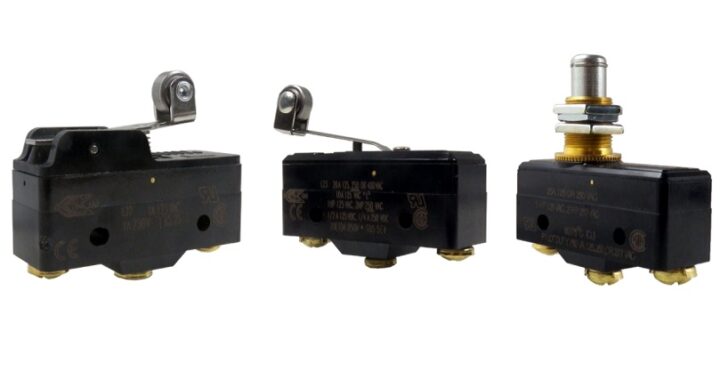 Types of Micro Switches and Their Applications
  Best Voltage Testers for Home Use: 2023 Edition
  Advantages of Transducers for Optimal Measurement
  Advantages of Infrared Sensors: Improved Accuracy and More