
What is a Signal Converter? Guide to its Functionality

What is a Signal Converter?
A signal converter converts electrical signals generated by sensors that take physical measurements such as temperature, frequency, current, resistance, voltage, pressure, level, etc. into standardized electrical signals, adapting them to PLC, DCS, and industrial control outputs.
The duty of a signal converter is to convert an analog signal into a different one, adapting it to control inputs/outputs or allowing for long-distance signal transmission without interference by means of galvanic separation.
The electronic signals that are detected by a detector can be completely different because of differences in the data that was measured. This makes it difficult to input the data directly into control circuits. Therefore, it is necessary to covert or normalize the data to a signal form that is easy to use.
There are various signal converters such as:
- Isolators.
- Sensor input converters.
- Distributors.
- Alarms.
- Pulse I/O converters.
- Characteristic converters.

What Does a Signal Converter Do?
Signal converters are used in small applications without a plc as control equipment as well as for isolation issues or conversion to standard signals in plc-controlled applications.
Generally, the benefit of a single device is that it can be operated and set up at any time directly without changing the software.
The transmission of analog signals in an industrial environment is very susceptible to interference, therefore:
- Modern signal converters prevent distortion of analog signals by external interferences.
- Voltage and current can be measured, converted, and isolating signals determined without any problem
- Galvanic isolation is a further must feature of an analog signal converter to de-couple the signals from the field and the expensive control equipment.
- Since most sensors are placed far away from the plc, a signal loss could easily happen, therefore converters are normally equipped with an amplifier to increase the transmission quality and therefore the quality of the control circuits.

Why Signal Converter is Used?
Reasons for using a signal converter:
- Measuring conversion.
- Standard signal conversion.
- Signal amplifying.
- Galvanic isolation. (optical/magnetically)
- Signal protection against environmental influences.
- Avoiding destruction by ground loops.
Physical processes and machine values (pressure, temperature, speed, resistance, …) have to be measured and converted into standardized signals for further processing and process controlling, i.e. converters are measuring a physical value and convert it into a standardized signal – they do the norming of a physical value.
For example:
A temperature of a mixing vessel needs to be monitored via a plc. The temperature is determined via a PT100 temperature sensor, which changes the resistance according to the Temperature. The range of such a sensor is very wide; typically -200°C to 850°C. By definition the resistance at 0°C is 100Ohm.
The monitored temperature should be displayed in a range between 0°C to 200°C and the display is equipped with an analog 0-10V Input, therefore a measuring converter is used. The measuring converter adjusts the measured signal (practically: reduces the range from -200 … + 850°C to 0 … 200°C, which results in a much higher precision of the display and transforms the signal into a standard signal ( 0..200°C Ohm to 0..10 Volt)

Most sensors (level sensors, pressure sensors, flow sensors, etc) release already standard signals. Complex measuring sensors have already a built-in measuring converter.
Nevertheless very often the existing standard signals cannot be processed by the control electronic due to different reasons, therefore the (existing) standard signal must be converted into another standard signal.
The different existing standard signals in accordance with the international directive IEC 751 (0-10 V, 0-20 mA, 4-20 mA, +/- 10 V, …) have to be converted into other from the controlling equipment required standardized signals, i.e. a standard input (e.g. 4-20 mA) is converted into a standard output (e.g. 0-10 V).
For example:
The level of a tank is determined with an ultrasonic level sensor. The sensor already converts the level signal into a 4-20mA output signal but the plc which controls the tank volume can only process 0-10V Input signals. A standard signal converter is needed to convert the 4-20mA into a 0-10V signal.

Very often sensors, actuators, and control devices (plc) are placed at far distances from each other but the control signals from the sensor to the controller and from the controller to the actuators are very often not very powerful.
Those signals have to be amplified so that the input resistance (load) of the connected equipment (for example measuring cards of PLCs) can be “driven”.

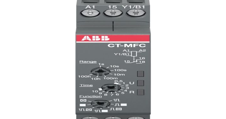 Types of Timer Relays and Their Applications
 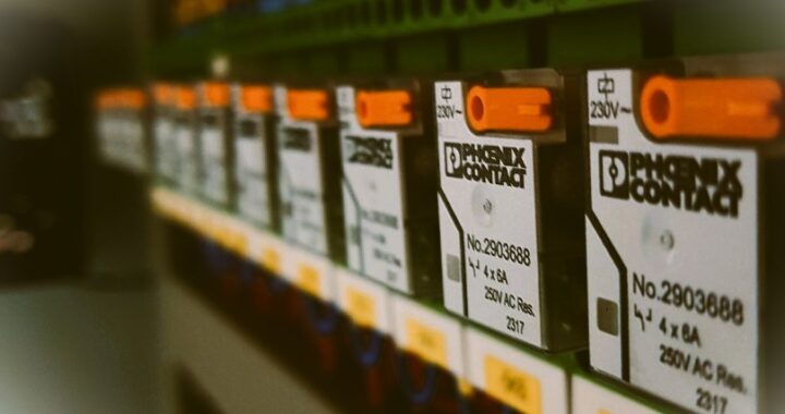 Relay Applications: Real-Life And Industrial Examples
 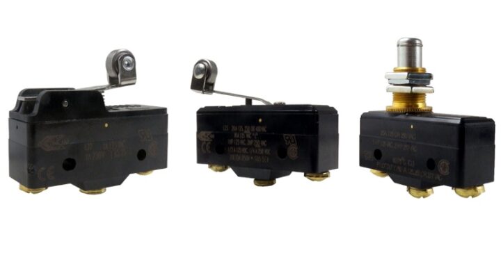 Types of Micro Switches and Their Applications
 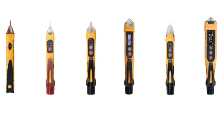 Best Voltage Testers for Home Use: 2023 Edition
  Advantages of Transducers for Optimal Measurement
  Advantages of Infrared Sensors: Improved Accuracy and More