
What is a Rheostat? Working Principle, Types, Applications

Rheostats, also known as variable resistors, play a crucial role in various electrical systems and applications. They are used to control the flow of current in a circuit by changing the resistance value. In this article, we will delve into the definition of a rheostat, its working principle, its different types, and its various applications in the real world. Understanding the concept of rheostats is important for electrical engineers and technicians as they are commonly used in various industries, including lighting, heating and motor control.
What is a Rheostat?
The rheostat is a variable resistor used to control the electric current by increasing or decreasing the resistance manually. It is a large-sized resistor type used in applications that require current adjustment or resistance change. It is placed in series in a circuit. The current controlled by rheostat is greater than other variable resistor types.
Two variables determine the electric current flowing through an electrical circuit. The amount of voltage applied to the circuit and the total resistance of the electrical circuit. If we reduce the resistance of the circuit, the amount of electric current through the circuit will increase. If we increase the circuit resistance, the current in the circuit will decrease.
The function of a rheostat in an electric circuit is to increase and decrease the electric current. It only reduces the electric current to a certain level and does not block it completely. An infinite resistance is required to completely block the flow of electric current. Practically it is not possible to completely reduce the electric current to zero.
Rheostats are made up of high-resistivity material, like, nickel-chromium iron alloy closely wound over a circular tube. These are available both in a single tube and double tube. Inter-turn insulation is provided to avoid short-circuiting turns. The tube of rheostat is made of insulating material, like asbestos.
The origin of the word rheostat comes from the Greek words “rheos” and “statis”. When these words are combined, they mean “flow control device” or “current control device”.

How Does a Rheostat Work?
The basic principle that rheostat use is Ohm’s law which states that current is inversely proportional to resistance for a given voltage. This means the current decreases as the resistance increases or increases as the resistance decreases.
Current enters the rheostat through one of its terminals, flows through the wire coil and contact and exits through the other terminal. It does not have polarity and operates the same when the terminals are reversed.
The structure of the rheostat is similar to a potentiometer. Because it is already a kind of potentiometer. Like the potentiometer, it consists of three terminals: terminal A, terminal B, and terminal C. However, only two terminals are used: A and B or B and C.
(2 of the terminals are connected to the opposite ends of a resistive element. 3rd terminal is located in between the other 2 terminals.)
Terminal B is the fixed terminal attached to the dial. A and C terminals are also connected to the resistive element. Moving along the resistive element, the wiper changes the resistance of the rheostat. The resistive element in the rheostat is made from a wire coil or a thin carbon film. The resistance of the rheostat depends on the length of the resistance wire through which the electric current flows.

If A and B terminals are used, the minimum resistance is taken when we move the wiper closer to terminal A; because the length of the resistance path is reduced. As a result, only small amounts of electric current are blocked and large amounts of electric current are allowed.
Similarly, when we move the wiper closer to the C terminal, maximum resistance is obtained; because the length of the resistance path increases. As a result, a large amount of electric current is blocked and only a small amount of electric current is allowed.

Types of Rheostats
Rheostat types are divided into three. Rotary, linear and preset.
1. Rotary rheostats
The resistive element in the rotary rheostat is circular or angled. In this type of rheostat, the wiper rotates. These are mostly used in power applications. Due to their small size, rotary rheostats are used more than linear rheostats.
2. Linear rheostats
They are also called cylindrical rheostats; because the resistive element is similar to a cylinder. In this type of rheostat, the wiper moves in linearly. Linear rheostats are often used in research and development laboratories.
3. Preset-type rheostats
Preset rheostats are used in PCBs. These are small in size and frequently used within calibration circuits.
Rheostat Applications
The rheostat is still used in some applications, although its usage area has decreased in recent years due to reasons such as low efficiency and consumption of energy and it has been replaced by switching electronic devices, semiconductor elements and potentiometers.
- The rheostat is generally used in applications where high voltage or current is required. Microwave oven, refrigerator, mixer, fan, power tools, etc.
- In dimmer switches, rheostats are used to change the intensity of the light. If we increase the resistance of the rheostats, the electric current flows less through the bulb and the brightness of the light decreases. Similarly, if we reduce the resistance of the rheostats, more electric current flows through the bulb and the light brightness increases.
- Rheostats are used to increase or decrease the speed of an electric motor.
- It is used in the buttons where the temperature setting of electric stoves is made. It is used in all applications similar to kitchen appliances that have heating elements that the temperature needs to be increased or decreased.
- It is used to increase or decrease the volume in devices such as TV and radio.
- It is used as etalon resistance in laboratories.
- It is used for resistance measurements with the bridge method.

Rheostat Selection
When choosing a rheostat for an application, the current is often a more important factor than power (watts).
If you use a rheostat for motor control, all direct current motor types can be speed-controlled; but you should know that only a few kinds of alternating current motor speeds are controllable. For this reason, it is necessary to use the rheostat in the correct type of engine.
Most rheostats have a round or straight shank that allows you to attach a handle to the rheostat.
Some of the smaller sizes have screwdriver slots that allow you to adjust the rheostat.
A switch can be connected to the rheostat to open the circuit or to access an independent circuit.
Rheostats can be controlled with a fixed or adjustable buffer that limits the angle rotation to any part of the total rotation. Generally, this type of rheostat is used in applications where a certain resistance is always required in the circuit.
 Types of Timer Relays and Their Applications
  Relay Applications: Real-Life And Industrial Examples
 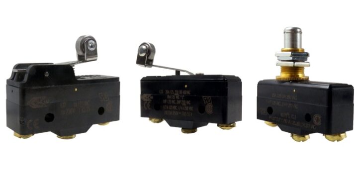 Types of Micro Switches and Their Applications
 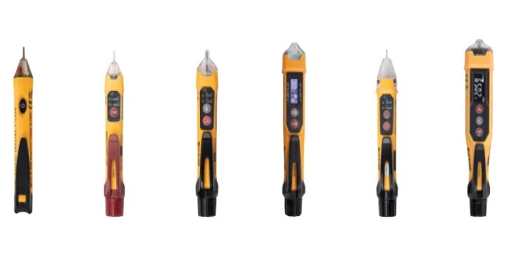 Best Voltage Testers for Home Use: 2023 Edition
  Advantages of Transducers for Optimal Measurement
  Advantages of Infrared Sensors: Improved Accuracy and More