
Different Types of Level Switches Explained Technically!

Level switches or level sensors are devices of various kinds from fully electronic to purely mechanical types with general usage in detecting if the level of a liquid has a definite height. The detection of the liquid level inside a tank is a common need in any industrial process, large or small.
For example, from large tanks in a petrochemicals refinery to small tanks in a brewery or water treatment plant, it is quite necessary to know if the liquid level has reached a high or low limit (level switches) or to measure continuously the value of the liquid level (level transducers). The same need exists for various granular materials of any kind inside a silo in many industrial applications while in the following the most representative basic types of level switches or sensors are described.
Types of Level Switches
The types of level switches are:
1. Electronic level switches
These are electronic devices that can, by using immersed electrodes, detect if the level of a conductive liquid is between two certain levels that the engineer can define according to the application needs. There are many examples of electrically conductive liquids encountered in industrial applications such as water, fruit juices, milk, beer, sewage, acids, alkaline solutions, etc.
The main device consists of the power supply circuitry (230 V AC, 50 Hz) including the voltage reduction to the required low voltages, the electronic circuit, the electrodes’ terminals and the SPDT contact output as shown in Figure 1.

Its operation requires the use of three-rod electrodes where one rod (E3) represents the earth connection and the other two electrodes (E1, E2) represent the upper and lower limits of the liquid level respectively. If the liquid tank is metallic, the earth electrode can be connected to any point of the metallic construction and therefore does not necessarily need to be immersed. The voltage applied to electrodes is an alternating one to avoid any possible electrolytic effect and is very low for safety purposes. The electronic circuit can detect if there is a current flow between electrodes through the liquid. The existence or absence of a current flow between the electrodes is converted by the electronic circuit, using a measuring amplifier and an electronic self-holding unit, to a switching contact alteration. Thus, the current detection is equivalent to the detection of the liquid level at the upper or lower level. It should also be noted that the behavior of the SPDT contact output is different during the level’s rise versus fall. As shown in Figure 2 when the level is rising and reaches the upper electrode (E1), then the contact output is activated. If the liquid level starts to fall, the output remains activated and will be deactivated only when the liquid level falls just below the lower electrode (E2).

When the electronic level switch is combined with a pump, either filling or emptying a tank automatically with its so-called “differential” behavior, the frequent and rapid start-stop repeated operation due to ripples on the surface of the liquid is avoided. Because of this differential behavior between the two-level limits and their electronic structure, the electronic level switches are sometimes called “level controllers”. Since the conductivity of the liquids can differ considerably, the response sensitivity of the electronic circuit detecting the current through the liquid is usually adjustable.
2. Capacitive level switches
The electronic level switches cannot be used in the case of non-conductive liquids or solid materials. The measuring system of level switches is capable of detecting liquids as well as bulk solid materials and is based on the capacitance measuring method. The capacitive level switch is a unified device that is side-mounted entirely on the tank walls, exactly at the ideal point, the level should reach. As shown in Figure 3, the device body is on the outside of the tank, while the projected set of the two capacitive electrodes is on the interior of the tank.

The first electrode is the sensitive one, meaning that it senses the presence of material, while the second electrode is called insensitive and usually is permanently connected to the earth (tank wall). The two electrodes are electrically isolated from one another by a suitable polyacetal material and form a capacitor with a dielectric material, the air. The operation principle of the capacitive level switch is based on the variation of the capacitance due to the presence of liquid or bulk solid material around the electrodes. In general, the capacitance C is directly dependent on the areas of the electrodes (A), their distance apart (D) and the dielectric constant (K) of the material between the electrodes defined as:
C = KA/D
When the tank is empty, then the capacitance (air dielectric) is C(K1). When the level switch is covered by material that plays the role of a dielectric substance filling the gap between the electrodes, the capacitance gets multiplied by the dielectric constant of this material (K2) and specifically varies to C´(K2) = e C(K1), where e is a constant expressing the difference of two dielectric constants. Its value is directly dependent on the material to be detected and indicatively has the value of 2–3 approximately for corn and 70–80 for water.
The variation in capacitance is subsequently translated into a switching output by an oscillating circuit, the frequency of which is dependent on the value of capacitance. The oscillation or stabilization of the circuit corresponds to the two states of the SPDT contact output and hence to the existence or absence of a material in the tank. The rod-type electrodes of a capacitive level switch are strong against the buried situation and therefore are suitable not only for fine powder but also for bulk solid materials. Since the temperature, moisture content, humidity and density of the process material can change its dielectric constant, the capacitive level switches are equipped with a sensitivity regulating mechanism for calibration. If more than one capacitive level sensor needs to be mounted in the same tank, a minimum distance between them should be provided by the manufacturer to avoid interference with their electromagnetic fields. Capacitive level switches can be used for level detection in silos, tanks and bunkers in all areas of industry for conductive or non-conductive liquids as well as for bulk solid material with a dielectric constant greater than that of air.
3. Ultrasonic level switches
Ultrasonic level switches and transducers work both on the same basic principle of generating and receiving after a target reflection of ultrasonic waves but are different in their output type. Ultrasonic level switches have a digital output signal of an SPDT contact type, while ultrasonic level transducers are capable of non-contact measuring the level through a microprocessor-based circuit and producing an analog output signal, usually 4–20 mA. Some ultrasonic level transducers offer both switch and current outputs which means they can be used either as a level switch or as a level meter. Ultrasonic-level sensors can detect liquids, sludge and solid materials.
An ultrasonic wave is a high-frequency acoustic wave that cannot be heard by someone. In general, people can hear an acoustic wave or sound if it is within the range of 20 Hz to 20 kHz. The transmitter of an ultrasonic level sensor emits acoustic waves usually within the range of 30 kHz to 200 kHz. The emitted ultrasonic waves hit the liquid, sludge, or solid surface and are reflected in the sensor as shown in Figure 4. The level is then calculated from the time lag between the emission and the reflection of the ultrasonic wave and is converted to a digital or analog signal accordingly. Ultrasonic level switches and sensors are sensitive to temperature, pressure and humidity conditions and for this reason, they are equipped with compensation units for reducing measuring errors. On the other hand, ultrasonic level sensors have some basic advantages over other technologies of level detection. For example, they can detect various materials that are quite far away, even more than 15 m. Also, the ultrasonic waves are not affected by the color of the target surface and its possible changes. The ultrasonic switch shown in Figure 4 uses a slightly different method to detect the presence or absence of a liquid at a designated point. It contains two piezoelectric crystals, one transmitting a high-frequency (about 2 MHz) sound and one receiving the previous sound, which is mounted opposite each other at a small distance of a few millimeters. The ultrasonic switch uses the different behavior of sound transmission in air and liquid to detect the liquid presence. When there is no liquid in the gap between the two crystals, the receiver accepts a weak signal, due to the sound transmission in the air which presents attenuation. When liquid is present, the sound retains almost all of its signal strength and the receiver accepts a strong signal. Subsequently, the electronics detect this difference and switch an SPDT contact output accordingly.

4. Radar-type level switches
Since it is difficult for the lag time-based method to give very accurate measurements for such small time intervals, the frequency-modulated continuous wave method is used in radar-type level sensors. A radar signal that is emitted via an antenna toward the liquid surface is a microwave signal with a continuously varying frequency. When the reflected signal returns to the receiver, it is compared with the outgoing signal. Since the transmitter continuously changes the frequency of the emitted signal, there will be a difference in the frequency between the transmitted and the reflected signals. The distance of the level from the sensor location (taking into account the dead zone) is then calculated by measuring the proportional frequency difference as illustrated in Figure 5.

5. Float level switches
The simplest level switches from a construction point of view are float-based level switches. In Figure 6 some basic types of float switches are shown. The float switch shown in Figure 6a requires sidewall mounting, while a similar one shown in Figure 6b is suitable for vertical placement. Both types use a sealed-in-glass magnetic switch and a floating part that contains a permanent magnet.
When the liquid level is low, the permanent magnet is far from the magnetic switch and thus its SPST contact is open. When the liquid level increases, the floating magnet is moved toward the magnetic switch. Once the magnetic switch is reached, the floating magnet activates the SPST contact which subsequently closes. Therefore, the floating magnet follows the changes in the liquid level and at a designated height, the contact output changes status and remains there as long as the level height does not change. Another type of float level switch is shown in Figure 6c where the two metallic plates play the role of an electric contact, and the metallic ball consists of the medium closing the contact. All the mentioned components are inside a plastic floating box, the orientation of which, up or down, depends on the liquid level height and determines the status, closed or open, of the contact.

6. Optical level switches
The optical level switch can detect the level of transparent liquids, while its operation principle is based on the refraction of infrared light through the liquid. Due to its very small dimensions, it is suitable for mounting in small devices for general use or containing small vessels of water or any other transparent liquid. Typical examples include switches used in drink vending machines, medical machines and devices, motor vehicle technology, etc. As shown in Figure 7a, the optical level switch consists of a plastic housing, a transparent hollow hemisphere, an infrared diode and a light-sensitive semiconductor. The infrared diode acts as a transmitter of a light beam and the semiconductor as a receiver of the light beam. When the switch is not covered by a liquid, the infrared light beam is fully reflected on the surface of the hemisphere and is guided to the receiver. When the switch is covered with a transparent liquid, the infrared light is mostly refracted into the liquid and less light reaches the receiver as shown in Figure 7b. The incidence or irregularity of the infrared beam on the receiver is then converted to a switching output that can be used suitably in an automation system.

 Types of Timer Relays and Their Applications
  Relay Applications: Real-Life And Industrial Examples
 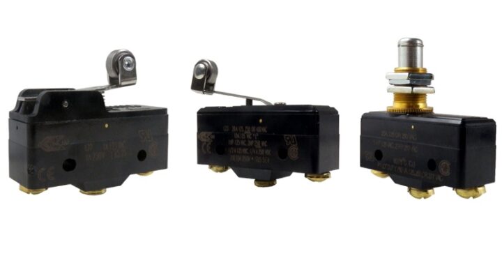 Types of Micro Switches and Their Applications
  Best Voltage Testers for Home Use: 2023 Edition
  Advantages of Transducers for Optimal Measurement
  Advantages of Infrared Sensors: Improved Accuracy and More